Internal Link Plan
- Die Casting Services
- Die Casting Guide
- Die Casting Mold Surface Treatment
- CNC Machining Services
- Single-Cavity vs Multi-Cavity Die Casting Molds
Content Differentiation Rules
This article is intentionally assigned one primary search intent. Do not optimize this page as a second general ‘die casting guide’. Use related terms naturally, but avoid making the primary keyword of another XINXIU page the main target here.
Introduction
The most effective die casting cost reductions often happen before a mold is manufactured. Once steel has been cut, a small geometry change can affect inserts, slides, cooling, electrodes, machining, trials and approval. Part design therefore has a direct economic effect on tooling complexity, casting stability and secondary machining.
This guide focuses on design decisions that can reduce manufacturing cost without turning the component into a low-quality compromise. It does not attempt to repeat a general die casting process guide or a cost-calculation article.
1. Review Function Before Geometry
Start by separating critical-to-function features from non-critical geometry. Mark sealing surfaces, bearing seats, mounting interfaces, datums, threads, alignment features and load-bearing areas.
This prevents the common mistake of applying tight tolerances, premium finishes or complex tooling features to every surface. The design target should be “right specification for the function,” not “maximum precision everywhere.”
2. Control Wall Thickness and Transitions
Large differences in section thickness can create thermal and filling challenges. They may also produce localized shrinkage, distortion or machining problems.
A more consistent structure is usually easier to cast. When extra stiffness is needed, ribs can often replace unnecessary solid mass. The goal is not to make every wall identical; it is to avoid abrupt transitions that create avoidable manufacturing problems.
3. Use Draft to Simplify Ejection
Draft helps the casting release from the die. Insufficient draft can increase ejection force, surface damage and tooling complexity.
Draft should be reviewed according to alloy, wall depth, texture and the actual mold-opening direction. Rather than applying one generic value to every face, review critical surfaces during DFM.
4. Make the Parting Line Practical
Parting-line location influences flash, ejection, appearance, machining access and mold construction. A small geometry change can sometimes move a feature into the pull direction and eliminate a side action.
When reviewing a CAD model, ask:
- Can the component open without an undercut?
- Can a mounting feature be moved to the fixed or moving half?
- Can the parting line avoid a visible cosmetic surface?
- Can machining access improve if the parting line changes?
A practical parting line is often a tooling-cost decision disguised as a geometry decision.
5. Minimize Slides and Side Actions
Slides, lifters and other moving mechanisms add components, machining, fitting and maintenance requirements. They are useful when an undercut is functionally necessary, but unnecessary side actions can increase both initial tooling cost and long-term maintenance.
Before approving an undercut, evaluate whether it can be removed, opened in the mold-pull direction, converted to a simple through-feature, or produced by a secondary machining operation.
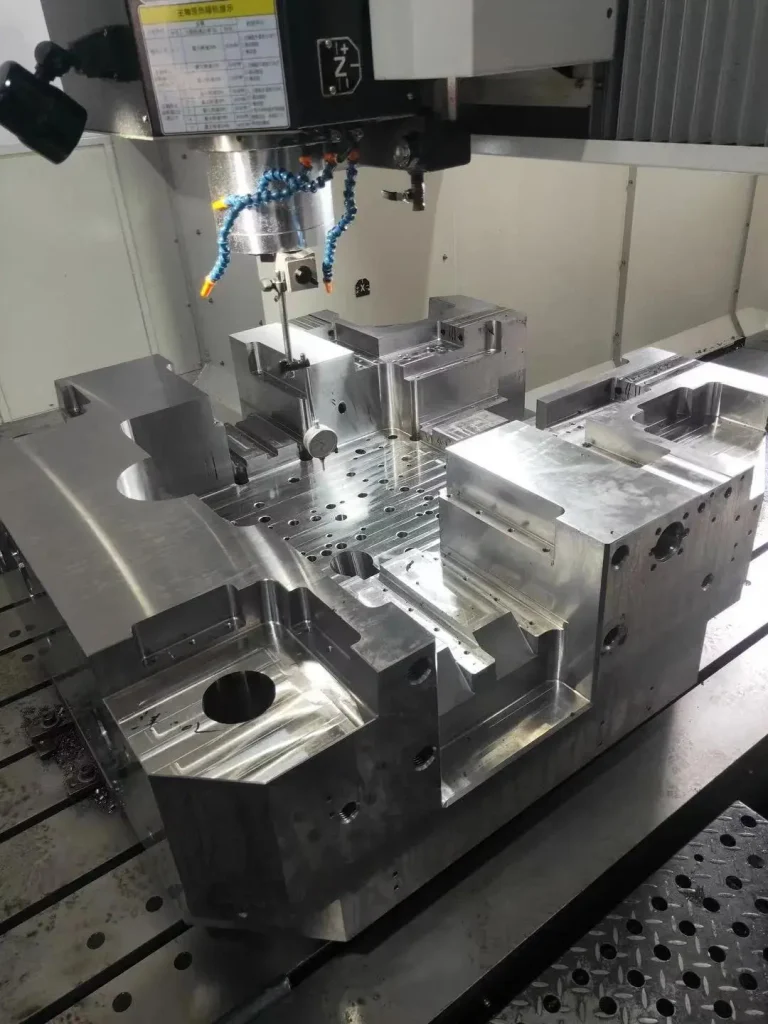
6. Design Critical Features for CNC Access
Die casting creates complex near-net geometry, but precision features may still need machining. The casting should make those operations easy.
Good practice includes:
- stable datums
- accessible hole orientations
- grouped features on common faces
- enough machining allowance on functional surfaces
- avoidance of deep, narrow pockets that require long tools
- locating surfaces suitable for repeatable fixtures.
A geometry that saves one CNC setup across tens of thousands of parts can create more savings than a small reduction in raw material weight.
7. Separate As-Cast and Machined Tolerances
Do not place a tight machining tolerance on an as-cast surface unless the process can realistically hold it. Conversely, do not force the mold to achieve a precision requirement that CNC can produce more economically.
A good drawing clearly identifies:
- as-cast dimensions
- machined dimensions
- critical datums
- geometric tolerances
- functional interfaces.
This lets the supplier design the mold and machining route as one system.
8. Avoid Over-Specifying Surface Finish
Not every surface needs polishing or a premium cosmetic finish. Identify visible zones and functional surfaces separately.
If powder coating, painting, anodizing, plating or polishing is required, define the final appearance early. Surface requirements can influence gate placement, ejector locations, trimming marks and post-processing.
9. Use Ribs Instead of Excessive Mass
A thick solid section may increase weight and complicate cooling. Ribs can provide stiffness with less material, provided their geometry remains suitable for filling and ejection.
The design should balance structural performance, casting behavior, machining requirements and appearance rather than optimize material usage alone.
10. Plan Machining Allowance With the Supplier
Too little stock can prevent a surface from being cleaned up after casting. Too much stock creates extra machining time and can increase distortion risk.
Machining allowance should be based on casting capability, feature size, expected variation and the required final tolerance. The allowance should be visible in the DFM discussion before mold manufacturing.
11. Identify Cosmetic Zones Before Tooling
A visible enclosure face is not equivalent to an internal mounting face. Mark cosmetic areas on the CAD model or drawing.
This gives the mold designer a chance to place gates, ejectors, overflows and parting lines where they have less visual impact. Trying to solve an appearance problem after the tool is built is usually more expensive than defining the requirement early.
12. Design Around Production Volume
A design intended for hundreds of prototype parts does not necessarily need the same tooling strategy as a program expected to run for years.
Production volume can influence:
- cavity count
- mold durability
- automation
- cooling design
- replaceable inserts
- cycle-time targets
- maintenance strategy.
The best design is the one that matches the commercial life of the program.
13. Review Material and Process Together
Aluminum, zinc and magnesium alloys have different density, flow behavior and functional characteristics. A design change that works for one alloy may not be ideal for another.
Material selection should therefore happen before the final DFM review. If the alloy is still undecided, the supplier should know which candidates are being considered.
14. Design for Quality Requirements
If the part needs leak testing, X-ray inspection, pressure resistance or controlled porosity, the design should identify those requirements before tooling.
For example, a sealing surface may need controlled machining, while an internal structural region may require inspection for internal defects. Quality requirements should influence feature design and process planning rather than be added at the end.
15. Cost Reduction Checklist
Before releasing a die casting design, ask:
- Are all tolerances functionally necessary?
- Can any undercut be removed?
- Can the parting line be simplified?
- Are wall transitions reasonable?
- Can ribs replace excess material?
- Can CNC features be accessed from fewer directions?
- Are machining allowances controlled?
- Are cosmetic zones clearly marked?
- Is the cavity strategy appropriate for forecast volume?
- Are inspection requirements defined?
16. When to Request DFM
The ideal time for a DFM review is before mold steel is committed. At that stage, changing a wall, moving a hole, relaxing a tolerance or removing an undercut can be relatively inexpensive.
XINXIU can review die casting drawings and 3D CAD data for design manufacturability, mold-flow considerations and downstream CNC requirements. Link this article to the Die Casting Services page and the Die Casting Guide, but keep the primary search intent focused on design-led cost reduction.
Conclusion
Die casting cost reduction should begin with the component, not with a request for a lower supplier margin. Practical draft, sensible wall transitions, fewer unnecessary side actions, realistic tolerances, accessible machining features and clearly defined cosmetic requirements can simplify the manufacturing route. A good DFM review turns those design decisions into measurable tooling and production advantages before the mold is built.
FAQ: What design changes reduce die casting cost most effectively?
Reducing unnecessary undercuts, simplifying parting lines, avoiding excessive tolerances and making CNC features accessible can reduce tooling and production complexity.
FAQ: Should every surface have a tight tolerance?
No. Tight tolerances should be reserved for features that control function, assembly, sealing or motion. Other dimensions can often use suitable as-cast requirements.
FAQ: Can CNC machining be used to simplify the mold?
Sometimes. A feature that would require an expensive side action may be more economical as a cast pilot feature followed by CNC machining. The decision depends on volume and geometry.
FAQ: When should DFM be performed?
Ideally before tooling is released for steel. Early DFM gives the engineering team the best opportunity to change geometry without expensive mold modification.
FAQ: How can a design reduce CNC cost?
Use stable datums, group features by machining direction, avoid difficult tool access and provide only the machining allowance that the final process needs.