Internal links included in article:
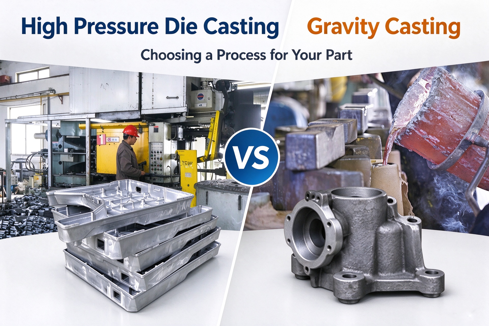
Choosing between high-pressure die casting and gravity die casting is not simply a decision about tooling cost or production speed. The wrong process can lead to incomplete filling, internal porosity, excessive CNC machining, failed leak tests, or tooling modifications after production has started.
For aluminum components, high-pressure die casting is often suitable for complex geometries, relatively thin walls, and repeat production at higher volumes. Gravity die casting can be a better fit for selected thicker-section parts, projects with moderate production volumes, or components that require a different balance of casting integrity, mechanical properties, and tooling investment.
The right decision depends on the actual part design, alloy, annual demand, critical dimensions, performance requirements, and total manufacturing cost.
This guide compares the two processes using practical engineering scenarios, indicative design parameters, cost calculations, and common manufacturing problems to help product engineers and purchasing teams make a more informed decision before releasing tooling.
1. High-Pressure Die Casting vs. Gravity Die Casting: The Key Differences
Both processes use reusable molds, but the way molten metal enters and fills the mold is fundamentally different.
High-pressure die casting (HPDC) injects molten metal into a steel die at high speed and pressure. It can produce complex shapes, integrated ribs, bosses, and relatively thin walls when the part geometry and filling system are properly designed.
Gravity die casting (GDC), also called gravity permanent mold casting, fills a reusable mold primarily through gravity. Filling is generally slower, so gating, venting, mold temperature, and feeding design are especially important for achieving sound castings.
| Comparison factor | High-pressure die casting | Gravity die casting |
| Metal filling | High-speed injection under pressure | Molten metal flows primarily under gravity |
| Typical design direction | Complex features and relatively thin, uniform walls | Moderate wall thickness and suitable, less filling-sensitive geometries |
| Indicative aluminum wall thickness | Approximately 1.5–4 mm for many designs | Approximately 3–6 mm for many designs |
| Production efficiency | Generally better suited to shorter cycles and higher output | Generally slower cycle and more dependent on casting size and cooling |
| Tooling investment | Often higher due to the injection system and tooling complexity | May be lower for suitable part designs, but depends on mold construction |
| Internal quality | Gas entrapment and porosity must be controlled through process and tooling design | Shrinkage, feeding, and solidification defects must be controlled |
| CNC machining | Useful for precise holes, mating surfaces, and threads | Also used where cast-in features cannot meet drawing requirements |
| Heat treatment | Conventional HPDC parts may blister or distort during heat treatment if gas porosity is present | Some gravity-cast alloys and processes are suitable for heat treatment |
| Common selection driver | Geometry, repeatability, output, and unit-cost reduction | Section thickness, performance requirements, and tooling economics |
Important: These wall-thickness values are preliminary design references, not guaranteed process limits. Alloy selection, flow length, projected area, mold design, local geometry, and casting equipment can change what is achievable. A drawing review and casting trial should confirm the final design.
2. Quantitative Design Parameters to Review Before Tooling
A useful process comparison must go beyond saying that one process is faster or cheaper. Engineers should review the parameters most likely to affect casting feasibility, machining cost, and final quality.
2.1 Wall thickness and uniformity
For many aluminum HPDC components, a nominal wall thickness around 2–3 mm is a reasonable starting point for early design discussions. Some designs require thinner sections, while larger or more demanding castings may need thicker walls.
For gravity die casting, approximately 3–6 mm is a useful preliminary range for many conventional aluminum components. Thinner walls may be possible in favorable designs, but the filling distance, alloy, mold temperature, and geometry must be evaluated.
The more important rule is to avoid abrupt changes in section thickness.
A thick boss connected directly to a thin wall may cool much more slowly than the surrounding material. This can create shrinkage porosity, surface sink marks, or local defects that become visible after machining.
Design actions:
- Keep wall thickness as uniform as practical.
- Use ribs to improve stiffness instead of making the entire wall thicker.
- Blend thick-to-thin transitions with suitable radii or tapers.
- Review isolated bosses and heavy sections before releasing the tooling design.
2.2 Draft angles and ejection
Reusable metal molds require draft so that the casting can be released without excessive friction, surface damage, or ejection problems.
As an initial design reference, many aluminum casting features use approximately 1–3° of draft, with internal walls, deep pockets, cores, and textured surfaces potentially requiring more.
The final value depends on feature depth, surface finish, alloy, mold coating, and the direction of mold opening.
A common customer problem is designing a deep pocket with nearly vertical walls to preserve the finished part dimensions. The supplier may then need additional polishing, a more complex core, or a tooling modification.
Before tooling approval, identify which surfaces are functional and which can accept draft. If a mating surface requires a tight dimension, it may be more economical to cast the feature with sufficient stock and finish-machine it afterward.
2.3 Dimensional tolerances and CNC allowances
As-cast dimensions and machined dimensions should not be treated as equivalent.
Casting tolerances vary with process, part size, mold construction, and the applicable drawing standard. A general tolerance should not automatically be applied to every feature without checking the supplier’s capability.
For critical features, define:
- The datum system and measurement method.
- Which dimensions are controlled in the as-cast condition.
- Which surfaces or holes require CNC machining.
- The machining allowance required for each critical surface.
- The final tolerance and surface-finish requirement.
For example, a mounting housing may have a relatively generous tolerance on its outer profile but require a tightly controlled bearing bore and flat mounting face. It is often more practical to cast the overall shape and machine only the functional features.
Do not specify unnecessarily tight tolerances across the entire casting. This can increase tooling costs, machining time, inspection requirements, and rejection risk without improving product performance.
2.4 Porosity and pressure-tightness requirements
Porosity is one of the most important factors when choosing a casting process.
High-pressure die casting can trap gas during rapid filling. Gravity die casting can develop shrinkage porosity when solidification and feeding are poorly controlled. Neither process automatically guarantees a defect-free internal structure.
The risk becomes especially important when the component must contain air, oil, coolant, water, or another pressurized medium.
If the part requires pressure-tightness, define the test pressure, medium, duration, allowable leakage, and inspection method before selecting the process.
For HPDC, vacuum-assisted casting, optimized gating and venting, controlled machining allowances, and impregnation may be considered where appropriate. For gravity casting, alloy selection, feeding design, mold temperature, and solidification control are important.
A casting that passes a visual inspection can still leak after CNC machining exposes internal pores.
3. Three Practical Engineering Scenarios
The following examples are representative engineering scenarios, not claims about completed XINXIU customer projects. They illustrate how the process decision changes with geometry, quantity, and performance requirements.
Case 1: A thin-wall aluminum electronics housing
Part profile
- Material: aluminum alloy, subject to final specification confirmation.
- Main wall thickness: approximately 2–2.5 mm.
- Features: ribs, mounting bosses, screw holes, and a relatively complex external profile.
- Demand scenario: 30,000 pieces per year.
- Main priorities: dimensional repeatability, appearance, assembly fit, and unit-cost control.
Likely starting point: High-pressure die casting
The relatively thin walls and integrated features make HPDC a strong candidate. Once the tooling and process are stable, the process can support repeat production and reduce the need to assemble multiple separate components.
However, the design still needs to be checked for filling distance, local thick sections, air entrapment, draft, ejector locations, and machining access.
Potential failure points
- A thick boss creates a local hot spot and increases porosity risk.
- A cosmetic surface is placed directly on a parting line or near an overflow.
- Mounting holes are designed with insufficient machining allowance.
- A supplier quotes the casting price without including CNC finishing or cosmetic rejection.
What to validate before approval
Request a DFM review, confirmation of the alloy, a proposed parting line, a machining plan for critical features, and agreed dimensional and appearance criteria. For visible surfaces, define the acceptable level of flow marks, ejector marks, and finishing variation.
When gravity casting may still be considered
If the design is simplified, the walls are increased, or annual demand is much lower than forecast, gravity casting may deserve a cost comparison. The decision should be based on actual mold quotations and qualified samples rather than geometry alone.
Case 2: A thicker aluminum housing with a leak-test requirement
Part profile
- Material: aluminum alloy selected for the required mechanical and environmental performance.
- Geometry: a thicker housing with fluid passages and machined sealing surfaces.
- Main priorities: pressure-tightness, stable machining results, and functional reliability.
- Production volume: to be confirmed from the actual demand forecast.
Possible starting point: Compare gravity casting and HPDC with a defined quality plan
Gravity casting may be worth evaluating when the geometry contains thicker sections and the performance requirements favor a carefully controlled solidification process. However, gravity casting is not automatically pressure-tight, and its suitability must be demonstrated through testing.
HPDC may remain viable when the design and process can meet the required leakage limit. Vacuum-assisted HPDC or other porosity-control measures may be considered depending on the component.
A common customer mistake
The buyer compares only the quoted price per casting and selects the cheaper option. After machining, some parts leak because machining has opened subsurface pores. The project then incurs rework, impregnation, additional testing, or scrap costs.
A better engineering approach
Before tooling release:
- Specify the actual operating pressure and required leak-test pressure.
- Identify sealing faces and critical passages on the drawing.
- Review whether critical passages should be cast into the part or machined afterward.
- Agree on the test method, sampling frequency, and acceptance criteria.
- Confirm whether impregnation is permitted and whether it affects the application.
- Evaluate the casting and machining route together.
Selection boundary
If pressure-tightness is essential, do not choose gravity casting solely because it is assumed to have lower porosity. Compare process capability and test results using the actual component design.
Case 3: A low-volume aluminum component with an evolving design
Part profile
- Annual demand scenario: 500–2,000 pieces.
- Geometry: a relatively thick component with a limited number of critical machined features.
- Design status: the customer expects several revisions after initial testing.
- Main priorities: controlled initial investment, engineering flexibility, and reduced risk from design changes.
Likely starting point: Compare gravity casting with other low-volume routes
Gravity casting may be economically attractive if its mold investment is lower for the particular design and the casting can satisfy the required properties. However, the actual economics depend on mold construction, cores, machining, finishing, inspection, and the number of revisions.
For very small quantities or an unproven design, rapid prototyping, CNC machining from solid material, or another prototype route may be more appropriate before committing to production tooling.
A common customer mistake
The customer releases a production mold before confirming the mounting interface, wall thickness, or internal clearance. The first trial reveals that the part cannot assemble correctly, and the mold requires welding, re-machining, or new inserts.
A better approach
Use a staged process:
- Confirm the critical interfaces and functional requirements.
- Review the 3D model and 2D drawing with the supplier.
- Prototype or validate key dimensions before production tooling where practical.
- Separate design-freeze requirements from features that may still change.
- Compare the cost of likely modifications against the cost of delaying tooling commitment.
Selection boundary
Lower annual volume does not automatically mean gravity casting is cheaper. If the component requires complex cores, tight tolerances, or extensive machining, the apparent tooling savings may disappear.
4. How to Compare Total Cost Instead of Unit Price
The most useful comparison is not simply the price of one casting. It is the total cost of delivering acceptable finished parts over the expected production life.
A practical cost model is:
Total program cost = tooling + casting production + CNC machining + finishing + inspection + expected scrap and rework + logistics
To compare the two processes fairly, request quotations using the same assumptions.
| Cost factor | Questions to ask the supplier |
| Tooling | What is included in the mold price? Are slides, cores, spare inserts, and trial runs included? |
| Casting price | What alloy and process assumptions are used? What is the quoted yield or scrap allowance? |
| CNC machining | Which dimensions require machining? Are fixtures and tool changes included? |
| Surface finishing | Is polishing, painting, coating, or another treatment required? |
| Quality control | Are dimensional reports, X-ray inspection, leak testing, or other tests required? |
| Tooling changes | What is the process for engineering changes after the mold is released? |
| Production capacity | What batch size, lead time, and delivery schedule can be supported? |
Illustrative break-even calculation
Assume, purely for comparison, that one process has a tooling cost of $20,000 and a finished-part cost of $4.00, while another has a tooling cost of $8,000 and a finished-part cost of $5.20.
The higher-tooling-cost route has an additional tooling investment of $12,000 but saves $1.20 per acceptable part.
The simplified break-even quantity is:
$12,000 ÷ $1.20 = 10,000 parts
Above 10,000 parts, the first route may have a lower combined tooling and part cost under these assumptions. Below 10,000 parts, the second route may cost less.
These figures are hypothetical and are not XINXIU quotations. The actual comparison must use supplier pricing and include scrap, machining, finishing, inspection, logistics, and any relevant change costs.
For projects with uncertain demand, ask suppliers to compare at least three volume levels—for example, prototype or pilot quantity, first-year demand, and expected lifetime demand.
5. Common Customer Mistakes That Increase Manufacturing Cost
Mistake 1: Selecting a process before the design is ready
A process chosen from a rough concept may become unsuitable after wall thickness, internal passages, mounting features, or performance requirements are finalized.
Better practice: Share the 3D model, 2D drawing, alloy requirements, annual volume, and critical dimensions before requesting a final tooling recommendation.
Mistake 2: Assuming thicker walls always improve strength
Excessively thick sections can increase weight, cooling time, and shrinkage-related defects. Adding material does not necessarily improve the casting’s structural performance.
Better practice: Evaluate ribs, section transitions, local loads, and the required mechanical properties. Use simulation or engineering review where the application justifies it.
Mistake 3: Machining too much material from a critical casting section
Machining can expose subsurface porosity that was not visible on the original surface. This is particularly risky around sealing faces, pressure passages, and other functional areas.
Better practice: Identify machining zones before mold design, control the machining allowance, and agree on pressure-testing and internal-quality requirements.
Mistake 4: Assuming gravity casting always produces better mechanical properties
Mechanical performance depends on the alloy, casting quality, section thickness, solidification, defects, and any approved heat-treatment route. The process name alone does not establish the final strength or fatigue performance.
Better practice: Specify the required property, test method, and acceptance criteria. Confirm that the chosen alloy and process can meet them on the actual part.
Mistake 5: Comparing quotations with different quality assumptions
One supplier may include CNC machining and inspection, while another quotes only the raw casting. The lower initial price may therefore lead to a higher finished-part cost.
Better practice: Use the same drawing revision, alloy, machining scope, finish, inspection plan, packaging, and delivery terms when comparing quotations.
Mistake 6: Ignoring future design changes
A tool optimized for a design that has not been validated can become expensive to modify. Slides, complex cores, and changes to critical interfaces may add significant cost and delay.
Better practice: Freeze the functional requirements first, validate the high-risk features, and agree on tooling-change procedures before production tooling begins.
6. When Is Each Process the Better Fit?
Use the following as an initial screening guide, not as a substitute for a DFM review.
| Your project requirement | Process to evaluate first | Why |
| Thin walls, integrated ribs, and complex geometry | High-pressure die casting | High-speed filling can support these features when properly designed |
| Stable, relatively high-volume repeat production | High-pressure die casting | Faster cycles can help reduce recurring part cost after tooling investment |
| Thicker-section geometry with suitable filling and feeding design | Gravity die casting | Gravity filling may be suitable for the component’s geometry and quality requirements |
| Lower initial tooling commitment | Compare gravity casting and prototype routes | Tooling economics depend on the part design and mold complexity |
| Pressure-tight or safety-critical component | Compare both against explicit quality requirements | Neither process guarantees performance without validation |
| Heat treatment is required | Evaluate the alloy and casting route carefully | Conventional HPDC may have limitations due to gas porosity; the complete process must be qualified |
| Design is still changing | Prototype and DFM review before production tooling | Early validation reduces the risk of costly mold modifications |
| Tight bores, flatness, or assembly interfaces | Evaluate casting plus CNC machining | Functional dimensions may need to be finished after casting |
7. What XINXIU Needs to Review Before Recommending a Process
A reliable process recommendation should be based on the component, not only its name or estimated quantity.
When requesting a manufacturing review, prepare the following information:
- 3D CAD model and 2D drawing: Include the latest revision and identify critical dimensions.
- Material requirements: Specify the alloy or the required mechanical, thermal, corrosion, and environmental performance.
- Expected quantity: Provide prototype quantity, annual demand, and estimated product life where available.
- Critical features: Identify sealing surfaces, threaded holes, bearing seats, mounting faces, and areas requiring CNC machining.
- Quality requirements: State leak-test conditions, dimensional inspection needs, appearance standards, and any applicable industry requirements.
- Finishing requirements: Include painting, coating, polishing, anodizing, or other post-processing requirements.
- Commercial priorities: Clarify whether the main constraint is tooling investment, unit cost, lead time, performance, or future design flexibility.
XINXIU can review the component requirements, evaluate the casting and machining route, and discuss whether high-pressure die casting, gravity die casting, or an alternative manufacturing approach is the most suitable starting point.
For related manufacturing information, see our Die Casting Services and Rapid Prototyping Services.
Conclusion
High-pressure die casting and gravity die casting solve different manufacturing problems. HPDC is often a strong candidate for complex, relatively thin-walled parts and higher-volume production. Gravity die casting may suit selected thicker-section parts, moderate production volumes, and projects where its tooling and quality characteristics fit the application.
The final choice should be based on wall thickness, filling and solidification behavior, alloy, dimensional requirements, pressure-tightness, machining, tooling investment, and lifetime demand.
The most effective way to reduce manufacturing risk is to review the part design and quality requirements before releasing the mold. A well-planned DFM review and a like-for-like total-cost comparison can prevent expensive tooling changes, machining defects, and avoidable production delays.
Need help selecting a casting process for your part? Send your 3D model, drawing, material requirements, and estimated annual quantity to XINXIU for a manufacturing review and quotation.
FAQs
Is high-pressure die casting always cheaper than gravity die casting?
No. HPDC can reduce recurring unit cost in suitable higher-volume production, but the initial tooling investment may be higher. The better option depends on tooling, machining, finishing, scrap, inspection, and expected lifetime quantity.
Which process is better for thick aluminum parts?
Gravity die casting may be suitable for some thicker-section parts, but thick sections can develop shrinkage porosity if feeding and solidification are not properly controlled. The actual geometry and alloy must be reviewed.
Can gravity die casting produce pressure-tight components?
It can be suitable for some pressure-tight applications, but pressure-tightness must be demonstrated through the specified test method. Process selection, casting design, machining, and inspection all affect the result.
Can high-pressure die castings be CNC machined?
Yes. CNC machining is commonly used for critical bores, threaded holes, mounting faces, and other precision features. Machining allowances and porosity risk should be considered before the tooling is designed.
Can high-pressure die castings be heat-treated?
Some conventional HPDC parts can develop blistering or other problems during heat treatment because of trapped gas. Suitability depends on alloy, process controls, part design, and the required treatment. The supplier should confirm and validate the proposed route.
What information is needed for a casting quotation?
Provide the 3D model, 2D drawing, alloy or performance requirements, annual quantity, critical dimensions, surface finish, inspection requirements, and expected delivery schedule. These details help the supplier make a more reliable process and cost recommendation.