Article
Introduction: Do Not Machine Every Surface
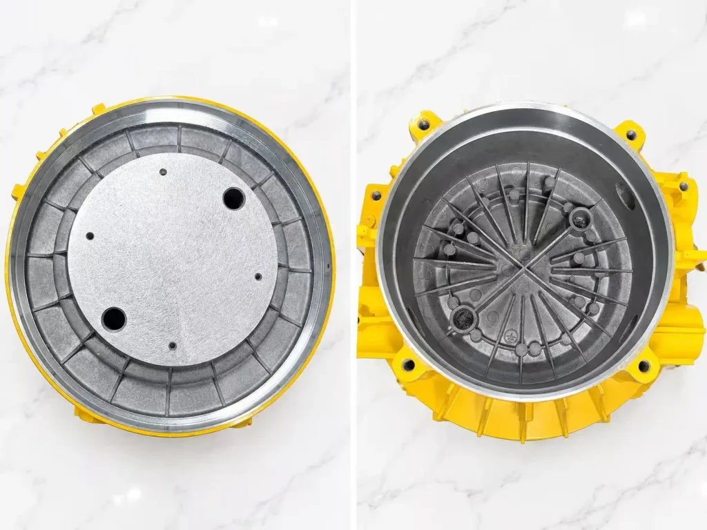
Die casting can produce complex near-net-shape components, but a near-net shape is not automatically a finished functional part. Bearing seats, locating bores, threaded interfaces, sealing faces, and mounting datums may need CNC machining to meet assembly or performance requirements. The cost-effective approach is to define which features control function, then coordinate the casting design, machining setup, and inspection plan before the die is released.
A common mistake is to add machining to every face “for safety.” That adds cycle time, tool wear, handling, and inspection without necessarily improving product performance. The opposite mistake—assuming every cast feature will be accurate enough—can create assembly problems or leaks. The decision should come from the drawing, operating conditions, and a manufacturability review.
1. Which Die-Cast Features Usually Need CNC Machining?
Start with function rather than appearance. Typical candidates include:
- Bearing seats and precision bores where shaft alignment, bearing fit, or concentricity affects performance.
- Mounting faces and locating datums that establish the position of the part in an assembly.
- Flat sealing faces and O-ring grooves where surface condition, flatness, or groove geometry affects sealing.
- Threaded holes and precision fastener interfaces, especially where thread quality or repeated assembly matters.
- Mating interfaces, counterbores, and selected slots or pockets that must locate another component.
Features that may remain as-cast include nonfunctional outer surfaces, ribs, bosses, and general contours when the casting process can hold the required geometry and finish. This is not a blanket rule: porosity risk, cosmetic requirements, tooling direction, and dimensional variation can change the decision.
2. Set Datums and Tolerances Before Tooling
The casting, fixture, machining program, and final inspection should reference a consistent datum scheme. For example, if a housing bore must align with a mounting face, the drawing should define that relationship explicitly rather than assigning a tight tolerance to the bore and leaving its position ambiguous.
Apply tight tolerances only where function requires them. A tolerance stack-up review can identify which dimensions control assembly and which can use a wider tolerance. Unnecessary precision increases machining time, inspection effort, and the chance of scrapping otherwise usable parts. Confirm the final tolerances with the product drawing and the supplier’s validated process capability; do not assume a universal tolerance applies to every casting.
3. How Much Machining Allowance Should a Die Casting Have?
Machining allowance is the extra material left on a cast surface so that CNC machining can clean up the surface despite expected casting variation. Too little stock can leave unmachined patches or fail to remove draft and surface irregularities. Too much stock can lengthen cycle time, increase tool wear, and create unnecessary chips.
There is no reliable single allowance for every die-cast part. The required stock depends on alloy, part size, local wall geometry, casting variation, datum strategy, fixture repeatability, and the amount of material removed. The engineering team should identify the critical machined zones on the 3D model, review expected variation, and confirm the allowance through supplier DFM and first-article inspection.
A practical review sequence:
- Mark critical-to-function surfaces and dimensions on the drawing.
- Define how the raw casting will be located and clamped for machining.
- Check whether the expected casting variation leaves sufficient stock at every point of the machined surface.
- Review tool access, cutter clearance, and the risk of thin walls moving under clamping force.
- Confirm the plan using first-article measurements and revise the casting or fixture if stock is inconsistent.
4. Porosity, Leak Risk, and Thin-Wall Distortion
CNC machining removes the outer skin of a casting. If pores or shrinkage-related defects are present below the surface, machining can expose them. This matters most at pressure-containing walls, fluid passages, and sealing faces. A part that looks sound before machining may still fail a leak test afterward.
For pressure-critical parts, agree on the acceptance criteria and validation method before production. Depending on the part and customer specification, this may include a defined leak test, pressure test, or radiographic inspection. Do not assume X-ray inspection is required for every component, and do not treat a visual check as proof of pressure integrity. The inspection method should match the risk and the drawing.
Thin walls can also distort if the fixture clamps them too hard or if material is removed unevenly. Support the part near the machining zone, use a stable locating strategy, and consider machining sequence and stress release where appropriate. If a sealing face or bore is critical, measure it after unclamping—not only while the part is held in the fixture.
5. Three Engineering Scenarios: Where the Decision Changes
The following are illustrative engineering scenarios to explain the decision logic. They are not represented as verified XINXIU customer cases or guaranteed production results.
Scenario A: A thin-wall electronics housing
A housing has a complex exterior, ribs, and several mounting bosses. The exterior contours and ribs may be left as-cast if their appearance and fit are acceptable, while the mounting datum and selected screw interfaces may need machining. If the design calls for a thin wall—for example, around 2–3 mm in a local area—do not assume the wall is automatically suitable for every casting design. Alloy, flow length, rib layout, gate and overflow design, and the actual geometry all affect fill and defect risk. Review the wall with the casting supplier and avoid machining away material that supports the housing.
Scenario B: A pressure-containing housing with a sealing face
The functional risk is not simply whether the sealing face is flat; it is whether the finished wall remains sound after material is removed. Define the sealing geometry, machining stock, datum relationship, and leak-test requirement together. If the design allows a machined face to cut too deeply into a wall that may contain porosity, revise the local geometry or the process plan before tooling. The acceptance standard should be agreed with the customer rather than inferred from a generic industry rule.
Scenario C: A low-volume part with many precision features
For a low-volume product or a design that is still changing, the economics may differ from a stable, high-volume part. A casting tool may reduce per-part material and machining demand at scale, but tool cost and design-change risk matter. For an early prototype, CNC machining from billet or a prototype route may be worth comparing before committing to production tooling. Compare the total route—including tooling, machining, inspection, lead time, and expected design revisions—not just the quoted price per part.
6. A Simple Cost Example: Why Extra Machining Adds Up
Consider a hypothetical comparison, not an XINXIU quotation: Route A uses a casting tool costing $20,000 and a $4.00 part cost; Route B uses a lower-cost tool at $8,000 but a $5.20 part cost because it needs more machining. The initial tool-cost difference is $12,000, while Route A saves $1.20 per part. The simple break-even quantity is $12,000 ÷ $1.20 = 10,000 parts, before financing, scrap, inspection, logistics, or other differences.
This example shows why the cheapest tool or the lowest machining time alone does not determine the best route. Use your own quoted tooling and piece prices, expected volume, quality requirements, and design-change assumptions to calculate the break-even point.
7. Common Customer and Supplier Planning Mistakes
- Finalizing the die before agreeing which surfaces will be machined. This can leave insufficient stock or inaccessible tool paths.
- Tightening every tolerance instead of identifying critical-to-function dimensions. This raises cost without necessarily improving assembly.
- Machining a sealing face without discussing porosity and leak validation. This can turn a hidden casting issue into a finished-part failure.
- Using the wrong datum strategy. A bore may meet its diameter tolerance but still be misplaced relative to the mounting face.
- Ignoring fixture deformation. A thin wall can measure correctly while clamped and move after release.
- Comparing quotations that include different operations or inspection levels. Confirm whether tapping, deburring, surface finishing, leak testing, and reports are included.
- Treating a sample part as proof of stable production. Agree on first-article approval and the ongoing inspection plan for critical features.
8. A Practical DFM Checklist Before Requesting a Quote
- Provide the latest 3D CAD model and 2D drawing, including revision level.
- Identify critical-to-function features, datum references, and required tolerances.
- Mark sealing faces, pressure boundaries, bearing seats, and threaded interfaces.
- State operating pressure, media, temperature, assembly conditions, and any leak-test criteria that apply.
- Ask the supplier to identify proposed machined surfaces and explain the machining sequence.
- Review machining allowance, fixture access, thin-wall support, and the risk of exposing porosity.
- Define first-article inspection, material or process documentation, and any special validation required.
- Compare total cost at the expected annual volume, including tooling, machining, inspection, finishing, and likely design changes.
How XINXIU Can Support the Project
For a project that combines die casting and secondary machining, review the casting geometry and the final functional dimensions as one manufacturing plan. Share the 3D model, drawing, annual volume, critical features, and operating requirements so the team can assess which features should remain as-cast and which need CNC machining.
Related services: Die-casting services
Precision CNC machining services
Conclusion
The right amount of CNC machining is the minimum needed to protect function, fit, sealing, and repeatability—not the maximum number of surfaces that can be cut. Define datums and critical tolerances early, set machining allowance through DFM, plan for porosity and fixture distortion, and validate the finished part against its real operating requirements. Coordinating casting and machining before tooling is complete is usually easier than correcting the design after production begins.
FAQs
Should all holes be machined after die casting?
No. Some holes or openings can be cast or partially formed. Precision bores, threaded holes, and interfaces that control assembly may need machining. The decision depends on the drawing, function, process capability, and inspection requirements.
Can CNC machining cause a die-cast part to leak?
Machining can expose subsurface porosity or remove material from a pressure boundary. For pressure-critical parts, define the machined zones and leak-validation method before production, then verify the finished component against the agreed acceptance criteria.
When should CNC machining be discussed?
During initial design-for-manufacturing review, before the die is finalized. That is the best time to align the datums, machining stock, fixture strategy, and inspection plan.
Is more machining always more accurate?
No. Additional machining can improve selected dimensions, but it also adds setups and opportunities for datum-transfer error or thin-wall distortion. Machine the features that require it and design a stable process around them.