
📌 Engineering Summary – Key Takeaways for Designers and Buyers
- Boss design determines 80% of riveting performance — most failures originate from stress concentration, not the riveting process itself.
- Ultrasonic riveting is fast but brittle; heat staking offers better stability for high‑volume production; cold forming is used for heat‑sensitive components.
- Material choice matters: ABS and PP are forgiving; PC and glass‑filled nylon require careful parameter control.
- Mold design (gate, cooling, venting) directly impacts boss integrity — internal stresses created during molding often cause cracking during assembly.
- Quantified design rules: wall thickness ≥ 1.0 mm, root radius ≥ 0.25 mm, draft angle 15–30°, and a D/d ratio of 1.5–2.5.
- Typical assembly yield target: ≥ 99.5% in stable production with proper DFM and process validation.
1. Why Plastic Riveting Is Widely Used in Mass Production
Plastic riveting is a fast, automatable joining method that provides stable joint strength at low assembly cost. It is not a mere cost‑saving alternative to screws or adhesives; in many industrial applications, it delivers a better balance between assembly speed, structural consistency, and automation compatibility.
However, experienced manufacturers recognize a critical reality: In high‑volume production, assembly stability is often more important than individual joint strength. Riveting eliminates torque variation, thread wear, and part‑count complexity by converting the joint into a single‑step forming process.
1.1 Riveting vs. Screws vs. Adhesive Bonding
| Method | Assembly Speed | Automation Level | Structural Consistency | Long‑term Stability |
|---|---|---|---|---|
| Screws | Medium | Low–Medium | Medium | Thread fatigue / loosening |
| Adhesives | Slow | Low | Variable | Aging / temperature sensitive |
| Plastic Riveting | High | High | High | Stable in mass production |
2. How to Select the Right Plastic Riveting Process
Different riveting processes are not interchangeable. Selection depends on material behavior, energy tolerance, and production volume. The three main methods are ultrasonic riveting, heat staking, and cold forming.
2.1 Ultrasonic Riveting – Fast but Sensitive
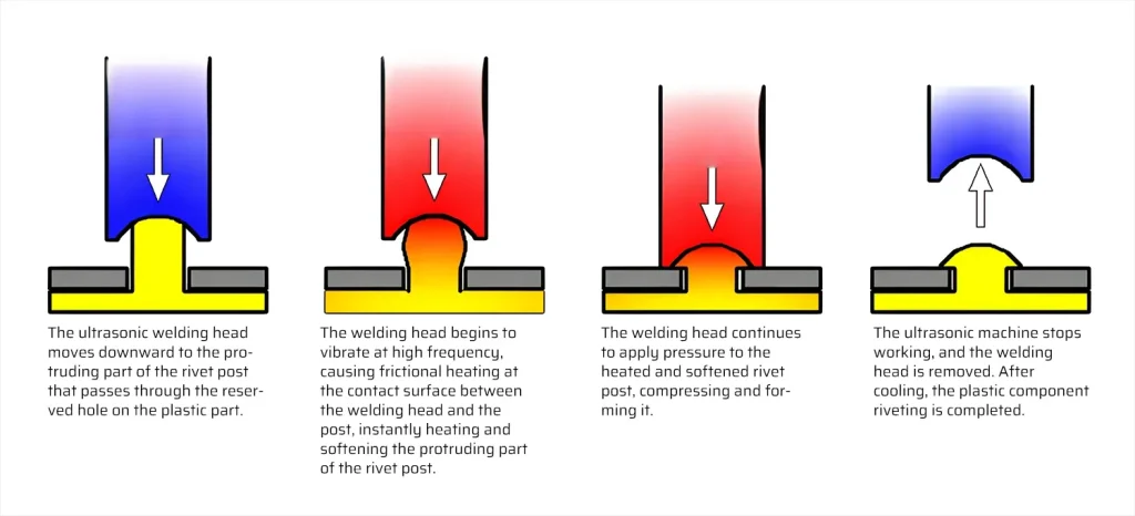
Ultrasonic riveting uses high‑frequency vibration (typically 20–40 kHz) to generate localized heat. It is widely used but often misapplied.
- Best for: ABS, PS, PP (limited), and some flexible materials.
- Limitations: Not suitable for brittle or glass‑filled materials; sensitive to boss geometry variation.
- Typical parameters: Amplitude 20–40 µm, weld time 0.2–1.5 s, pressure 0.2–0.6 MPa.
2.2 Heat Staking – The Most Stable High‑Volume Solution
Heat staking (thermally forming a rivet head) is widely used in automotive and appliance production because it provides controlled melting and low stress.
- Advantages: Lower stress concentration than ultrasonic; more forgiving on boss variation; suitable for structural joints.
- Typical parameters: Heating temperature 20–40°C below material melting point (e.g., ABS: 180–220°C, PC: 220–260°C); forming time 1–3 s; cooling time 1–2 s.
2.3 Cold Forming (Mechanical Riveting)
Used when thermal input is not allowed – e.g., optical components or heat‑sensitive electronics.
- Limitations: Requires high‑precision fixturing; joint strength depends heavily on material ductility.
- Typical pressure: 0.5–1.0 MPa (depending on material and boss size).
2.4 Process Selection Matrix
| Material | Recommended Process | Risk Level | Notes |
|---|---|---|---|
| ABS | Ultrasonic / Heat staking | Low | Stable, good flow |
| PC | Heat staking | Medium | Crack risk under ultrasonic |
| PA66 (Nylon) | Heat staking | Medium–High | Moisture control required |
| POM | Mechanical / Ultrasonic (limited) | Medium | Sensitive to energy input |
| Glass‑filled Nylon | Heat staking (preferred) | High | Tool wear + stress concentration |
Engineering insight: Most failures in production come from wrong process selection rather than poor execution. Always validate with sample trials.
3. Boss Design – The 80% Factor
In real production, riveting failure is rarely caused by the process itself. It is almost always a structural design problem at the boss level. Boss design determines stress distribution, cooling behavior, and energy absorption.
🔍 Industry insight: Most boss cracking occurs due to internal stresses created during mold cooling, not during riveting. If cooling is uneven, the boss already contains micro‑cracks before assembly starts.
3.1 Key Boss Design Parameters (With Quantified Data)
| Parameter | Recommended Range | Function / Effect |
|---|---|---|
| Wall thickness (t) | ≥ 1.0 mm (min 0.8 mm for small parts) | Prevents cracking under load |
| D/d ratio (boss outer/inner diameter) | 1.5 – 2.5 | Balances strength and flexibility |
| Draft angle | 15° – 30° | Improves ejection and reduces stress |
| Root radius | ≥ 0.25 mm (recommended 0.5 mm) | Reduces stress concentration at base |
| Boss height / diameter ratio | ≤ 3:1 (avoid slender bosses) | Prevents buckling under side load |
Design example: For a boss with inner diameter 4 mm (d), outer diameter should be 6–10 mm (D). Wall thickness = (D-d)/2 = 1–3 mm. Use a root radius of 0.5 mm to distribute stress. Always simulate filling and cooling to verify.
4. How Mold Design Affects Riveting Performance
Even with perfect geometry, mold design determines whether production is stable or inconsistent. Three critical areas are gate position, cooling, and venting.
4.1 Gate Position Controls Structural Strength
Poor gate placement can cause weak boss density, flow hesitation, and weld line formation. Place the gate to ensure uniform filling and avoid flow‑induced molecular orientation that weakens the boss root.
4.2 Cooling Design Controls Shrinkage and Sink Marks
Hot spots around bosses are the most common root cause of sink marks and micro‑cracks. Use conformal cooling or baffles to keep boss temperature within ±10°C of the nominal mold temperature (typically 40–80°C for amorphous plastics, 80–120°C for semi‑crystalline).
4.3 Venting Prevents Air Traps
Without proper venting, air traps form inside the boss, causing inconsistent density and weak joint strength. Venting depth should be 0.02–0.04 mm for most thermoplastics.
5. Material Selection for Riveting Applications
Material choice determines whether the joint survives long‑term stress, vibration, and thermal cycling. Higher strength does not always mean better riveting – brittleness is often the limiting factor.
| Material | Behavior | Riveting Risk | Typical Tensile Strength (MPa) |
|---|---|---|---|
| ABS | Balanced toughness and flow | Low – excellent | ~40 |
| PC | Strong but brittle | Medium – crack risk under ultrasonic | ~65 |
| PA66 (Nylon) | Strong, moisture‑sensitive | Medium – dimensional changes | ~80 |
| POM | Low friction, stable | Medium – energy‑sensitive | ~60 |
| Glass‑filled Nylon (30% GF) | High stiffness, low ductility | High – stress concentration | ~150 |
Recommendation: For critical riveted joints, conduct a small‑scale trial with the actual production material and process to validate boss integrity.
6. Common Failure Modes and Root Causes
Failure analysis is more valuable than process description. The table below links failure modes to design and process issues.
| Failure Mode | Root Cause | Design Issue | Process Issue |
|---|---|---|---|
| Boss cracking | Stress concentration | Thin root radius / sharp corners | Excessive ultrasonic energy |
| Sink marks | Cooling imbalance | Thick boss wall | Poor mold cooling |
| Weak joint strength | Low energy transfer | Insufficient boss volume | Wrong process (e.g., ultrasonic on glass‑filled) |
| Misalignment | Fixture tolerance | Poor datum design | Assembly positioning errors |
Diagnostic tip: If cracks appear only after storage or thermal cycling, the root cause is likely internal molding stress – not the riveting process.
7. Industrial Applications of Plastic Riveting
- Automotive interior – door panels, dashboard assemblies, air vents
- Consumer electronics – housings, battery covers, display frames
- Appliance components – washing machine parts, kitchen appliances
- Medical devices – enclosures, disposable assemblies
In many cases, riveting is chosen not because it is strongest, but because it is the most consistent option in mass production.
8. Manufacturing Workflow for Riveted Plastic Products
- DFM analysis – review boss geometry, wall thickness, and draft.
- Mold design review – gate, cooling, and venting validation.
- Injection molding trial – produce sample bosses and measure dimensions.
- Boss structural testing – pull‑off or push‑out tests to determine baseline strength.
- Riveting process development – optimize energy, time, pressure.
- Assembly line validation – run pilot batch (500–1000 pieces) to confirm yield.
- Final inspection and SPC – monitor key parameters (rivet height, pull strength).
Typical timeline: 4–8 weeks from DFM to production release, depending on complexity.
9. How to Evaluate a Plastic Riveting Supplier
When selecting a manufacturing partner for riveted assemblies, use this checklist to ensure technical capability.
DFM report provided with boss design optimization
Material recommendations with quantified data (strength, shrinkage)
Mold flow and cooling simulation for critical bosses
Process validation plan (DOE, parameter window)
Inspection criteria for rivet height, pull force, and visual quality
Ability to handle multiple riveting methods (ultrasonic, heat staking, cold)
Proven track record in your industry (automotive, medical, electronics)
Clear quality control documentation and traceability
10. Frequently Asked Engineering Questions
What is the real strength limit of plastic riveting?
Depends on boss geometry and material – typical pull‑off forces range from 50 N (small PP) to over 500 N (large PA66 with optimal design).
Why do bosses crack during assembly?
Most cases originate from internal molding stress (poor cooling or gate placement), not assembly force.
Can riveting replace screws completely?
Not if disassembly or maintenance is required. Riveting is permanent; screws allow service access.
How do I choose between ultrasonic and heat staking?
Use ultrasonic for high‑speed, low‑stress applications (ABS, PS). Use heat staking for brittle or glass‑filled materials, or when boss geometry varies.
What is the typical yield target in production?
≥ 99.5% first‑pass yield is achievable with proper DFM, process control, and automated monitoring.
11. Conclusion
Plastic riveting is a highly effective assembly method when designed and executed correctly. The key to success lies in understanding that boss design, material selection, and mold quality are far more influential than the riveting process itself.
By following the design rules, process selection matrix, and validation workflow outlined in this guide, engineering teams can achieve strong, consistent joints with minimal scrap – and significantly reduce time‑to‑market.
Final advice: Always perform DFM analysis and a small‑scale trial before committing to high‑volume tooling. Invest in cooling optimization and process monitoring. The cost of prevention is always lower than the cost of rework.
Need Expert Guidance on Your Plastic Riveting Project?
Submit your part design or 3D model for a free DFM review. Our engineering team will assess boss geometry, material suitability, and process options – and provide a detailed report with actionable recommendations.Request Your Free DFM Review →
Turnaround within 48 hours. No obligation.
Disclaimer: This guide provides general technical information based on industry standards and engineering best practices. Actual results depend on specific materials, equipment, and production conditions. Always validate with trials and consult qualified engineers for project‑specific decisions.