For hardware OEMs and engineering product managers, the journey from a verified CAD model to a high-volume product is riddled with invisible technical traps. A functional prototype that performs flawlessly on a workbench can easily become an unmanufacturable nightmare when moved to a mass-production assembly line.
The key to protecting your unit economics and accelerating time-to-market lies in Design for Manufacturability and a deep understanding of process transitions. This technical guide analyzes the critical engineering pivot points when scaling from high precision CNC machining services to mass injection molding and die casting.
1. Prototyping Baseline: Isotropic CNC Machining vs. Anisotropic 3D Printing
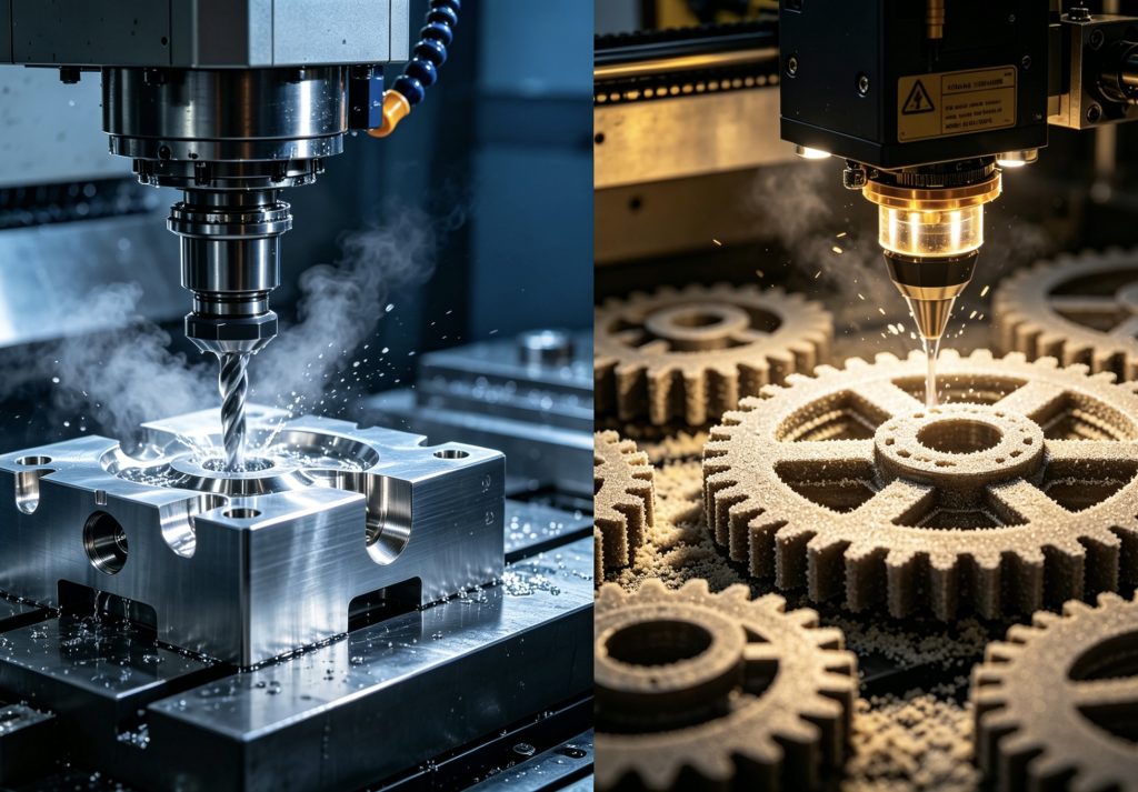
In the early stages of the hardware lifecycle, rapid prototyping and low volume manufacturing often rely on either CNC machining or 3D printing (SLA/SLS).
The Material Physics of Prototyping
- CNC Machining: A subtractive process utilizing raw, extruded blocks of production-grade materials (e.g., Al6061-T6, PEEK). The mechanical properties are isotropic, meaning the tensile strength and shear resistance are identical across all axes.
- 3D Printing (SLA/SLS): These are additive processes. Parts exhibit anisotropic tendencies—the bonds between deposited layers are inherently weaker than the solid material within a single layer.
Tolerances and Dynamic Testing
CNC can comfortably hold linear tolerances of ±0.005 mm required for press-fit bearings or dynamic seals. SLA can achieve stunning cosmetic surfaces but will distort under thermal load.
Engineering Takeaway: Never evaluate dynamic structural fatigue using an SLA prototype. If your part must endure cyclical mechanical stress, machine an as-machined CNC baseline prototype.
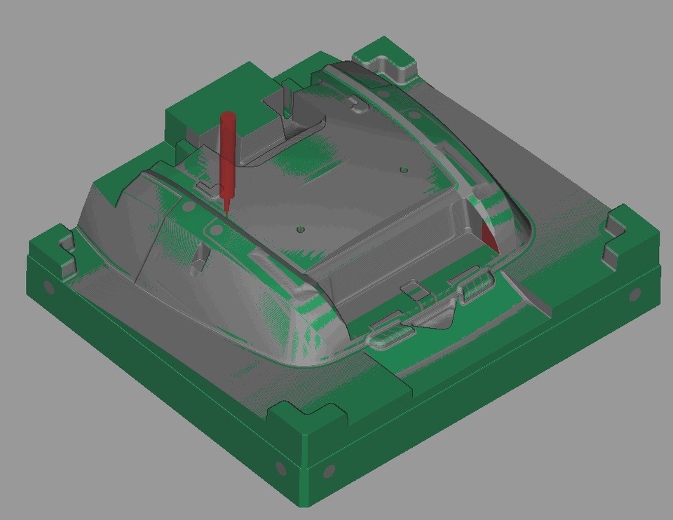
2. CNC Machining to Injection Molding Transition: The DFM Guidelines
The most common point of supply chain failure occurs during the CNC machining to injection molding transition. CNC allows for thick walls and sharp internal corners; injection molding strictly forbids them.
The Uniform Wall Thickness Mandate
Plastic is a poor conductor of heat. When molten polymer is injected into a mold cavity, thick sections cool slower than thin sections, creating internal volumetric shrinkage. This results in two catastrophic defects:
- Sink Marks: Superficial depressions on the cosmetic face of the part.
- Internal Voids: Vacuum pockets inside the thick wall that compromise structural integrity.
To apply proper DFM guidelines for injection molding, you must core out thick sections, maintain a uniform nominal wall thickness, and utilize reinforcing ribs. As a rule of thumb, rib thickness should not exceed 60% of the nominal wall thickness to prevent sink marks.
Draft Angles and Ejection Physics
An injection mold must physically eject the plastic part from a steel core. Without a draft angle, the friction generated during ejection will scrape or crack the part surface.
- Untextured walls: Minimum of 0.5° to 1.0° draft.
- Textured surfaces (VDI 3400): Require 1.5° to 3.0° of draft per side for light textures to prevent dragging.
3. Bridge Tooling: Mitigating Risks via Rapid Tooling Low Volume Production
When your design requires validation with real production resins (like glass-filled nylon) but your initial market demand is only 500 to 5,000 units, rapid tooling low volume production serves as your strategic safety net.
Rapid Tooling vs. Production Tooling Cost
Evaluating rapid tooling vs production tooling cost is essential for procurement heads:
- Rapid Tooling: Uses high-grade aluminum (7075-T6) or pre-hardened steel inserts inside a modular Master Unit Die (MUD) base. Tool fabrication times drop from 6 weeks to 10–14天, saving up to 60% in upfront capital.
- Engineering Compromise: To eliminate automated mold complexity, complex internal undercuts are resolved via hand-loaded inserts (pick-outs). This increases injection cycle time but slashes initial tool costs.
4. Scaling to the Million-Shot Domain: High-Volume Production Molding
When your product scales past 10,000 units into mass market territory, the manufacturing focus shifts to cycle-time optimization and tool longevity.
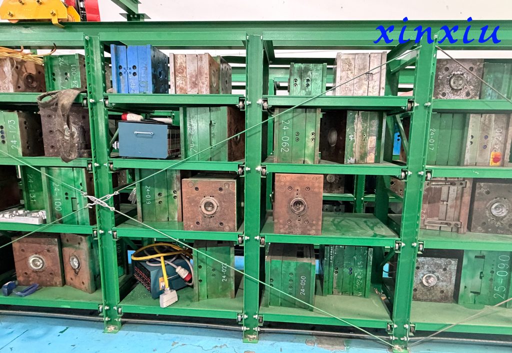
Tool Steel Metallurgy
High-volume production tools require premium steels capable of enduring extreme clamping pressures and abrasive resins.
- P20/NAK80 Steel: Good for up to 100,000 cycles; easily polished for high-gloss parts.
- H13/420 Stainless Steel: Heat-treated to over 50 HRC, these steels resist the abrasive wear of glass-fiber-reinforced plastics (e.g., PA66-GF30) and easily survive 1,000,000+ cycles.
Advanced Thermal Management
- Hot Runner Systems: Eliminate waste (the sprue and runner) by keeping plastic molten all the way to the gate.
- Conformal Cooling: Utilizing 3D-printed steel inserts, conformal cooling channels curve around the geometry of the part, ensuring uniform thermal dissipation and eliminating part warpage.
5. Transitioning to Metal: Die Casting vs. Injection Molding Strength
When a product requires extreme mechanical strength, thermal dissipation, or built-in EMI/RFI shielding, engineering plastics fail. At this junction, you must evaluate die casting vs injection molding strength.
Managing Porosity in Die Casting
Die casting utilizes Aluminum (A380/ADC12), Magnesium, or Zinc alloys. Unlike polymers, molten metal travels at much higher velocities, introducing gas and shrinkage porosity. High-end die casting mitigates this through:
- Vacuum-Assisted Venting: Pulling air out of the cavity before injection.
- Hybrid Workflow: Due to thermal contraction, die casting cannot achieve ultra-precise alignment tolerances. The component is cast slightly undersized, and a secondary 5-axis CNC machining center precision-mills the critical faces and bores the high-tolerance holes.