
To address the issues of defects—such as porosity, shrinkage cavities, shrinkage porosity, and cold shuts—that commonly occur in automotive aluminum alloy transmission housings during the die-casting filling and solidification processes, this study analyzes and optimizes the product structure, die-casting machine selection, gating system, and mold design, using an automotive aluminum alloy transmission housing as an example. This product is made of A380 aluminum alloy, with a net weight of 6.5 kg and an average wall thickness of 4.5 mm; the mold cores are made of DIEVAR material. The product contains numerous internal oil passages, which impose high requirements on the internal density and airtightness of the casting. Acceptance criteria stipulate that the porosity must not exceed 5%, the size of any gas holes must not exceed 3 mm, and the casting must pass subsequent high- and low-pressure leak tests.
To address variations in product wall thickness, oil passage structures, and complex lateral forming areas, the project first selected a die-casting machine based on the product’s projected area and injection pressure ratio, and determined the injection system in conjunction with a φ140 mm injection chamber. Subsequently, the gating system was optimized to ensure that the molten metal could enter the mold cavity in a more rational and stable manner, and CAE filling analysis was conducted to verify the molten metal flow, filling speed, and final convergence zone. Building on this foundation, multiple core-pulling mechanisms were designed to meet the product’s lateral forming requirements, and DIEVAR core inserts were adopted to enhance the mold’s stability during high-temperature, high-pressure die-casting. By adjusting process parameters—including mold preheating temperature, molten aluminum pouring temperature, injection speed, and boost pressure—and validating them through actual die-casting production, the team ultimately produced an aluminum alloy transmission housing that met internal quality and airtightness requirements, thereby laying the groundwork for stable mass production.
Product Design and Die-Casting Requirements
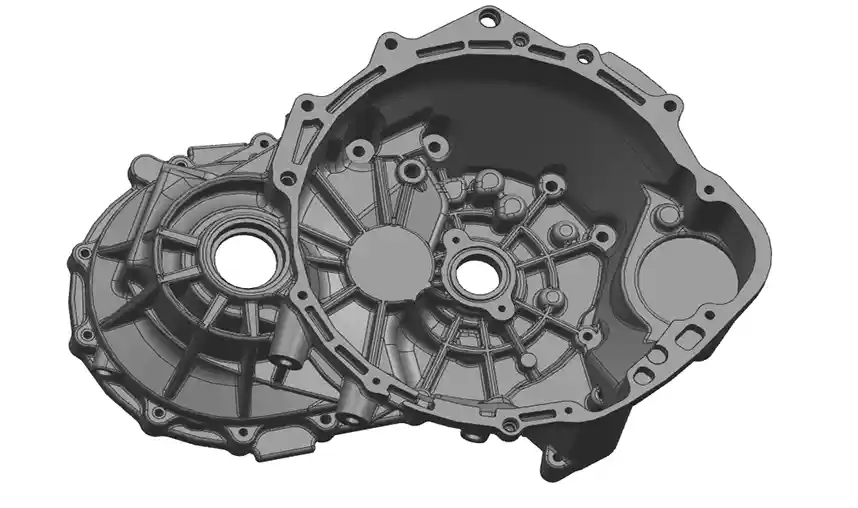
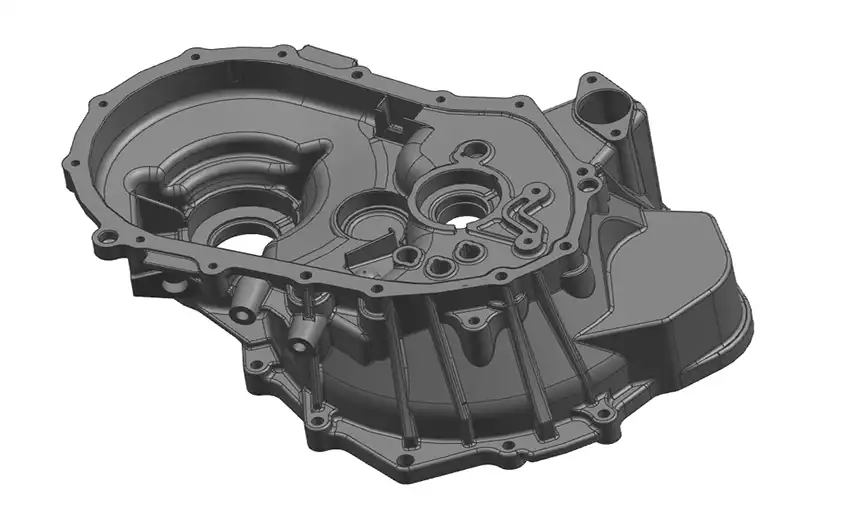
The product’s overall dimensions are 507.82 × 358.86 × 143.28 mm, with a net weight of 6,505.98 g and an average wall thickness of approximately 4.5 mm. The product has a complex overall structure, with numerous oil passages, holes, and reinforcing structures distributed throughout its interior and periphery; there are significant differences in wall thickness and molten metal flow distances across different areas.
In particular, the oil passages and certain sealing areas must provide fluid sealing after subsequent CNC machining; therefore, in addition to ensuring the complete formation of the product’s external shape and hole locations, it is essential to strictly control internal defects such as gas pores, shrinkage cavities, and porosity. The project’s sample submission requirements stipulate that the casting’s porosity must be controlled within 5%, with gas pore dimensions not exceeding 3 mm, and that the casting must pass high- and low-pressure leak tests after subsequent machining.
Therefore, the die-casting process for this project cannot simply prioritize rapid filling; rather, it must comprehensively consider the interrelationships among molten metal flow, venting, solidification, and pressure-assisted shrinkage compensation to ensure that the product meets the requirements for forming quality, internal density, and airtightness despite its complex structure.
Die Casting Machine Selection and Gating System Design
Based on the product design and die-casting requirements, the first step is to select the appropriate die-casting machine. The clamping force of the die-casting machine is verified primarily based on the total projected area of the casting and the gating system on the parting line, the injection pressure ratio, and the safety factor.
The maximum projected area of the product’s outer dimensions is first calculated based on its length and width:
Product A = 507.82 × 358.86 = 1,822.36 cm².
Taking into account the additional projected area contributed by the gating system, overflow channel, and venting structure, the clamping force is verified during the design phase based on a total projected area of approximately 2,000 cm². The clamping force can be calculated using the following formula:
F_(clamp) ≥ K × P × A
where F_(clamp) is the required clamping force, K is the safety factor, P is the design injection pressure, and A is the total projected area of the casting and gating system.
For this project’s design phase, a safety factor of 1.2 was adopted, and the injection pressure was verified at approximately 60 MPa. Therefore:
F_(clamp)≥ 1.2 × 60 × 2000]
The calculation yields a required clamping force of approximately 14,400 kN. Taking into account the equipment specifications and production margin, a 1,600-metric-ton horizontal cold-chamber die-casting machine was selected for this project, equipped with a φ140 mm die chamber to provide sufficient equipment margin for the product’s injection capacity and filling process.
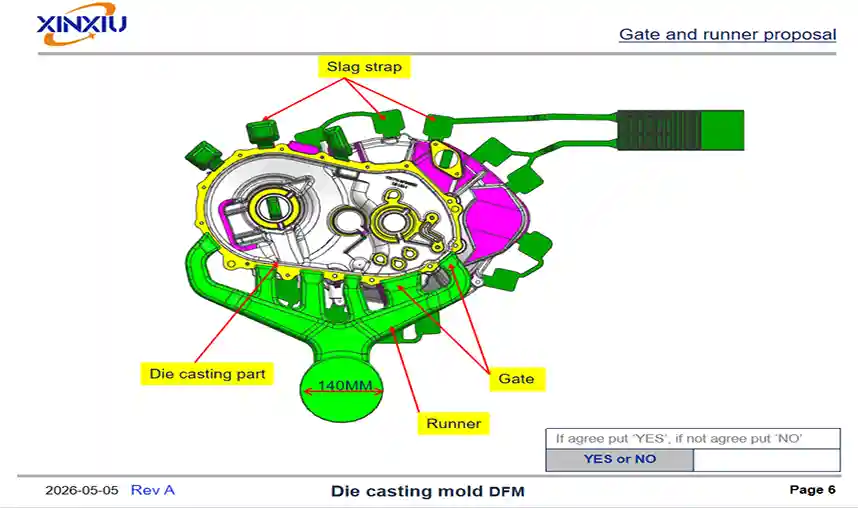
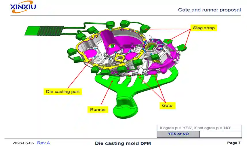
Once the die-casting machine has been selected, the gating system is designed based on the product’s wall thickness, the location of the oil passages, and the distance the molten metal must travel. The internal runner is the primary channel through which molten metal enters the mold cavity; its position and cross-sectional area directly affect the filling rate, flow direction, and final convergence pattern. For this product, it is necessary to minimize the effective flow distance of the molten metal while avoiding direct impact on critical cores and sealing areas.
The total cross-sectional area of the internal runner is first preliminarily calculated based on the mass flow rate of the molten metal:
Ag = G / (ρ × vg × t)
Ag represents the total cross-sectional area of the inner runner; G represents the mass of molten metal passing through the inner runner; ρ represents the density of molten A380 aluminum; vg represents the velocity of the molten metal in the inner runner; and t represents the effective filling time of the mold cavity.
The net weight of this product is 6505.98 g. Based on a preliminary verification using a density of approximately 2.7–2.74 g/cm³ for molten A380 aluminum alloy, an effective filling time of approximately 0.07 s, and a runner velocity of approximately 48 m/s—and considering only the mass of the product body—the calculated runner cross-sectional area is approximately 845–858 mm². This result serves primarily as a preliminary lower limit for the sprue area; actual design must also take into account the mass of molten metal in the cross-gates, overflow, and venting systems.
We then performed further verification using the continuity relationship for flow between the pressure chamber and the inner runner. The cross-sectional area of the φ140 mm pressure chamber is:
Ac = πD² / 4
Ac = π × 140² / 4 ≈ 15,394 mm²
During the pressure injection process, the volumetric flow rate of the molten metal as it passes through the pressure chamber and the inner runner should remain essentially constant; therefore:
Ac × Vc = Ag × Vg
where Vc is the high-speed velocity of the pressure injection plunger, and Vg is the velocity of the molten metal in the inner runner.
For this project, the high-speed injection velocity is set at approximately 4.5 m/s, and the target velocity in the inner runner is set at approximately 48 m/s. Therefore:
Ag = 15,394 × 4.5 / 48 ≈ 1,443 mm²
Therefore, based on the preliminary flow rate calculation for product quality and the velocity relationship between the pressure chamber and the internal runner, the total cross-sectional area of the internal runners for this project is preliminarily controlled within the range of approximately 1,400 to 1,450 mm². The dimensions and feed ratios of each internal runner will then be further optimized through CAE filling analysis.
CAE Filling Analysis and Pouring Strategy Optimization
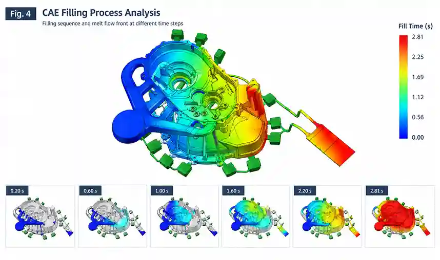
After completing the preliminary design of the gating system, XINXIU engineers used CAE to analyze the molten metal filling process, focusing on the flow direction, filling speed, convergence points, and final filling areas after the molten metal entered the mold cavity.
Due to the product’s long flow path and multiple oil passage structures, excessive differences in flow velocity between different feed locations can easily lead to premature solidification in certain areas and result in cold shuts or entrapped gas in the convergence zone. Therefore, the CAE analysis first examined the intermediate filling stage to confirm the advancement status of each stream of molten metal and adjusted the position and dimensions of the internal gates based on the flow conditions.
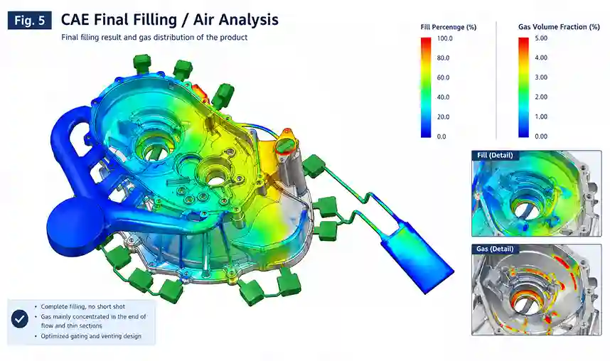
The optimized pouring system undergoes a final filling analysis, focusing on the final filling zones and potential air accumulation areas, to ensure that the molten metal front advances in the intended direction and to push gases within the mold cavity toward the overflow and venting zones as much as possible.
After optimizing the gating system through CAE analysis, the final design is then applied to mold structure design and actual trial molding. For large, complex transmission housings, a well-designed gating system not only determines the filling behavior of the molten metal but also directly influences the layout of sliders, core pull mechanisms, and cooling systems; therefore, the gating design and mold structure must be considered simultaneously. Similar cases involving large aluminum alloy transmission housings also highlight the direct impact of product structure and gating systems on mold structure design.
Mold Structure Design
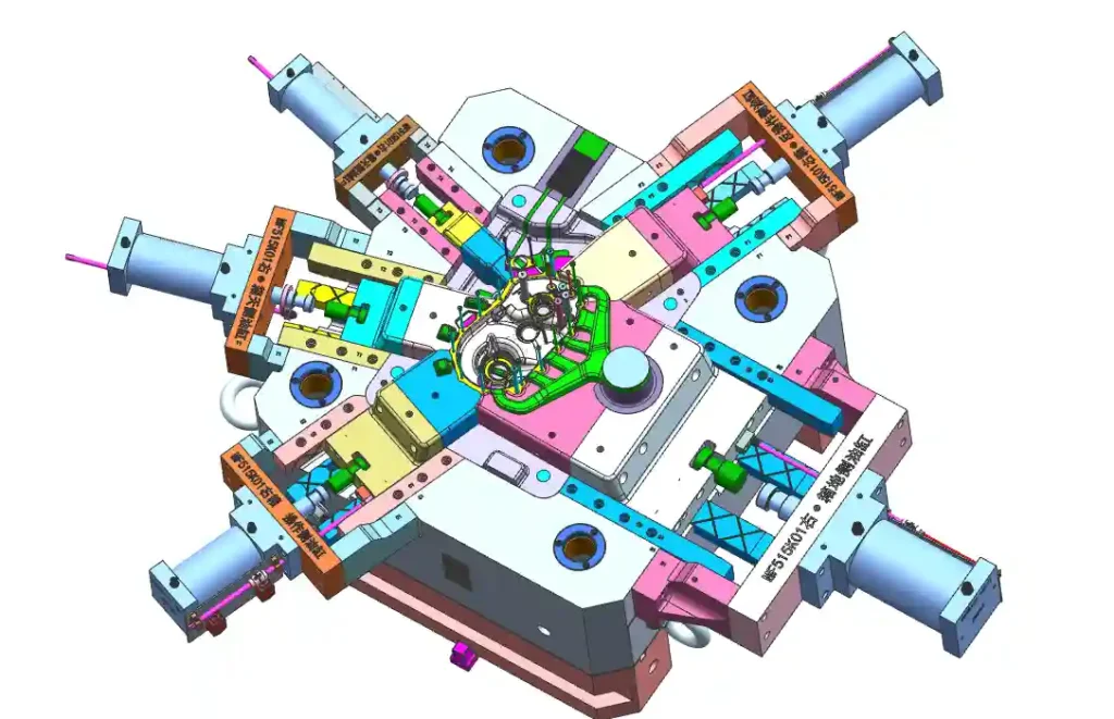
After determining the gating system, the mold structure was designed based on the product’s complex external contours, oil passages, hole locations, and lateral structures. Since there are multiple areas around the product’s periphery that cannot be directly formed along the main parting line, the mold employs multiple sets of lateral core-pulling mechanisms to achieve the formation of the complex structure.
The mold cores are made of DIEVAR material, with strength and cooling designs specifically focused on areas subject to high-speed impact from molten aluminum and areas of concentrated heat. The lateral core-pulling mechanisms are arranged according to the product’s hole locations and lateral structures, and are designed in conjunction with the direction of slider movement, core-pulling distance, clamping method, and mold opening sequence to ensure that each core-pulling mechanism can complete demolding according to the preset sequence of operations.
For core areas directly impacted by molten aluminum, reasonable structural design minimizes localized erosion; simultaneously, the mold cooling system controls cavity temperature to maintain a relatively stable thermal equilibrium during continuous die-casting, thereby reducing product forming variations caused by excessive localized temperatures or large temperature differentials.
Optimization of Die-Casting Process Parameters and Actual Production
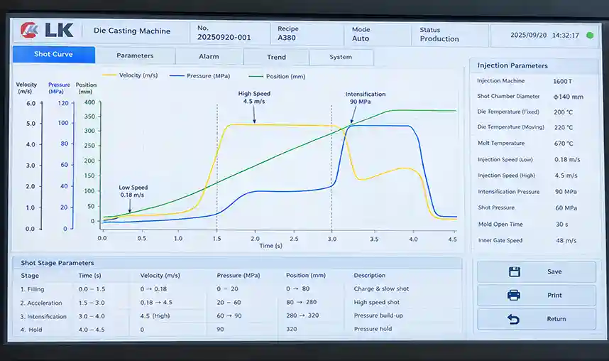
After completing the mold design, the die-casting process parameters were set based on the CAE analysis results and the product’s structural characteristics. Taking into account the fluidity of A380 aluminum alloy and the product’s average wall thickness of 4.5 mm, the fixed mold temperature was set to approximately 200°C, the moving mold temperature to approximately 220°C, and the molten aluminum pouring temperature to approximately 670°C to ensure smooth mold filling.
The injection process employs a combination of low-speed, high-speed, and pressurized injection. The low-speed injection velocity is approximately 0.18 m/s, allowing the molten metal to enter the injection chamber smoothly; the high-speed stage increases to approximately 4.5 m/s to rapidly complete cavity filling, with the molten metal velocity in the internal runner reaching approximately 48 m/s. The injection pressure ratio is designed and verified at approximately 60 MPa; after filling is complete, a boost pressure of approximately 90 MPa is applied to improve the casting’s solidification and shrinkage compensation, thereby enhancing the internal density of the oil passages and sealing areas.
Simply put, the entire injection process consists of low-speed advance → high-speed filling → pressure boost. During actual production, the low-speed to high-speed transition and the pressure boost process are monitored via the injection curve, and process parameters are adjusted based on the casting’s surface finish, flash, and X-ray inspection results.
After injection is complete, the mold is held closed for approximately 30 seconds, followed by automatic mold opening. Once the lateral core-pulling mechanism has completed core extraction, the ejection mechanism ejects the casting. A robotic arm then retrieves the casting, applies a release agent, and the process proceeds to the next die-casting cycle.
Finished Product Quality and Testing and Validation
The final die-cast product features a clear overall contour, with oil passages, holes, and major structural features fully formed; no obvious defects such as cracks or cold shuts were observed on the surface. To meet the product’s requirements for internal density, X-ray inspections were conducted on critical areas, focusing on internal porosity and shrinkage in the oil passages and areas to be machined subsequently, to ensure that the porosity rate and pore size met the project’s sample submission requirements.
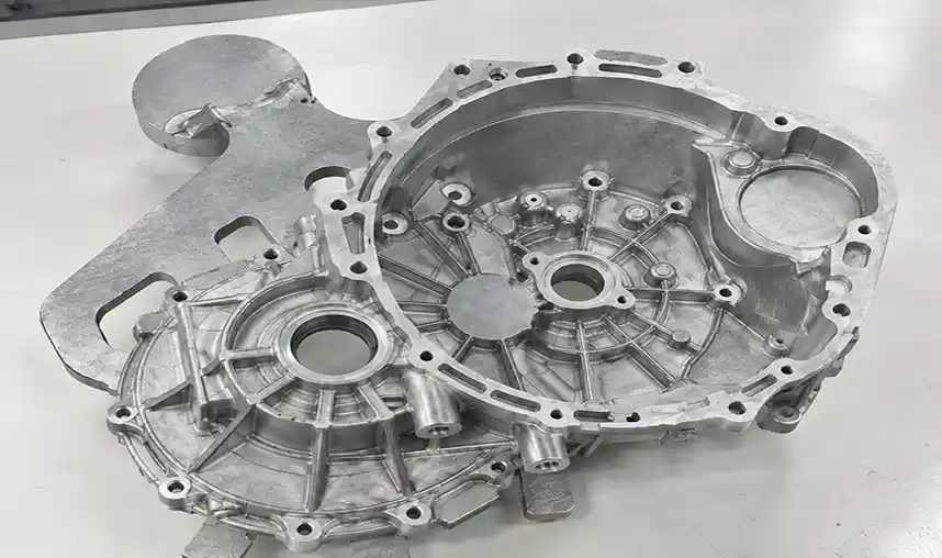
After the castings underwent subsequent CNC finishing, high- and low-pressure leak tests were conducted on critical sealing areas to verify the airtightness of the machined oil passages and sealing surfaces. Ultimately, through die-casting machine selection, pouring system optimization, CAE filling analysis, mold structure design, injection process optimization, X-ray inspection, and high- and low-pressure leak testing, the development and validation of this aluminum alloy transmission housing project were successfully completed.